Okay, the activity we did yesterday was to help us understand some basic circuit terminology, and more importantly, introduce us to the concepts of voltage, current, and resistance.
So what ARE voltage, current, and resistance?
Electric current is basically made up of flowing electrons (going back to basic chem). It helps to imagine that a wire is a hose, and that the electrons flowing through the wire is the water flowing through the hose.
Voltage (or electromotive force) is defined as the work required to move a charge between two points. Hose comparison: the pressure of the water, or the "pushing force." In English: The phrase "electromotive force" says it all. Electro- (electron) + motive (move) + force = work to move a charge. EMF is measured in Volts. Symbol: v, EMF
Current is the magnitude of the flow of charge. In English: The number of electrons flowing past a point per second. Hose comparison: the amount of water flowing through the hose per second. Current is measured in Amperes (one coulomb/second). Symbol: I (very strange, but true)
Resistance is defined as the opposition of a medium to the flow of electrons. In English:... that's pretty much it. Hose comparison: The tap on a hose, which changes the strength of a hose's pressure without changing the amount of water going through it. Symbol: Ω (Greek letter omega)
These three quantities are interrelated through a relationship called Ohm's law. Resistance is directly proportional to EMF and is inversely proportional to current.
This relationship is:
I * Ω = v
Where I is current, Ω is resistance, and v is voltage/EMF
Drawing a circuit: Tips
1. Wires are straight lines: it makes life less confusing for you. On my robotics team, we often have to make schematic diagrams of electronic and pneumatic systems, and they need to be simple - but accurate. That's exactly what you're shooting for when you draw a circuit diagram- even a moron should be able to read the diagram and know what you're talking about.
2. Make sure that positive and negative terminals are the right way around! A lot of electrical circuits work one way, but not the other- making sure that everything is the right way around is essential.
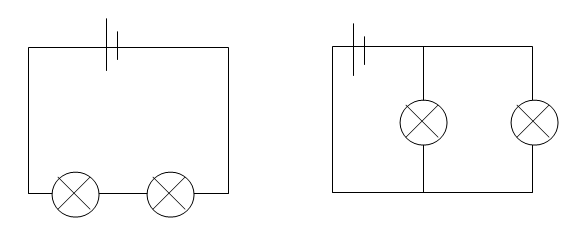
3. Parallel Circuits Vs. Series circuits: All circuits are NOT created equal. Two bulbs connected in series (left) are NOT the same as two bulbs connected in parallel (right). They have different voltages and current values.
4. Voltmeter position: Don't worry about this yet, but whenever we have to put voltmeters (they measure EMF) in a circuit diagram, they MUST be connected in PARALLEL!!! They tend to "eat" the voltage passing through them... why? Voltmeters have a huge resistance, meaning that there is a large voltage "drop" across a circuit with a voltmeter in it.
5. Use the right symbols: You have a list of electrical symbols in the IB data book thing. Use it!


